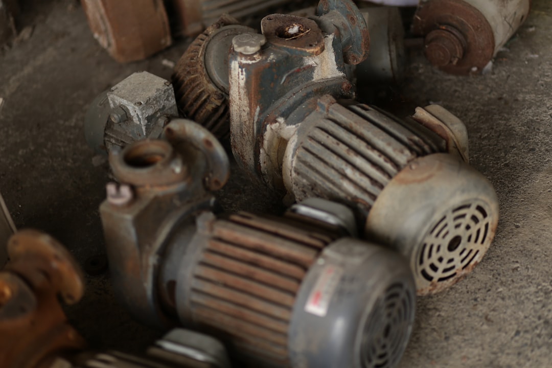
The hum of an electric motor is a familiar sound in modern life, powering everything from kitchen appliances to electric vehicles. Yet, behind this ubiquitous technology lies a fascinating and intricate process of creation, a journey from raw materials and precise engineering to the dynamic force that drives our world. Crafting electric motors is a testament to human ingenuity, a complex interplay of physics, materials science, and meticulous manufacturing. This article delves into the fundamental stages of this process, exploring the transformation of simple coils into the sophisticated mechanisms that harness electromagnetic principles.
At the core of every electric motor lies its electromagnetic heart: the coils of wire. These coils are not just simple loops; their precise construction and arrangement are paramount to the motor’s performance and efficiency. The materials used, the number of turns, and the way they are insulated all contribute to the magnetic field that will ultimately drive the motor.
The Choice of Conductors: Copper’s Dominance
The primary material for windings is almost universally copper. Its excellent electrical conductivity is crucial for minimizing energy loss as heat. However, not all copper is created equal.
High-Purity Copper: The Standard for Performance
For most electric motors, especially those requiring high efficiency and power density, high-purity, annealed copper wire is employed. This means the copper has undergone processes to remove impurities and become more ductile, making it easier to wind without breaking. The purity of the copper directly impacts its resistance, and thus the motor’s efficiency.
Aluminum as an Alternative: Balancing Cost and Conductivity
In some applications, particularly where cost is a significant factor and weight is less critical, aluminum wire might be used. While aluminum is less conductive than copper by volume, it is significantly lighter. Engineers must carefully account for the increased resistance and potential for expansion and contraction at different temperatures when using aluminum.
The Art of Winding: From Simple Loops to Complex Patterns
The process of winding the coils is a blend of automated precision and, in some cases, skilled manual labor. The complexity of the winding depends heavily on the type of motor being produced.
Stator Windings: The Stationary Field
In most electric motors, the stator is the stationary part, and its windings are responsible for generating the rotating magnetic field. Stator windings are typically embedded within slots machined into the stator core.
Drop Winding: A Common Method for Uniformity
A prevalent technique is drop winding, where lengths of insulated wire are fed through the stator slots in a specific pattern. The number of turns per slot, the wire gauge, and the interleaving of different phases are meticulously calculated to create the desired magnetic field. Automated winding machines ensure consistency and speed, vital for mass production.
Random Winding: For Simplicity and Cost-Effectiveness
For smaller, less demanding motors, random winding might be employed. In this method, the wire is fed into the stator slots without a precise pattern, relying on the density of winding to fill the available space. While less efficient and potentially less reliable than patterned windings, it is a more cost-effective solution for certain applications.
Rotor Windings: The Moving Component
The rotor is the rotating part of the motor, and its windings interact with the stator’s magnetic field. The nature of the rotor windings dictates the motor’s type and operating principle.
Squirrel Cage Rotors: The Backbone of Induction Motors
Many AC induction motors utilize a “squirrel cage” rotor. This design features conductive bars (typically aluminum or copper) embedded in a laminated iron core and connected at each end by conducting rings. No direct electrical connection is made to these bars; the magnetic field from the stator induces currents within them, creating the torque. The winding here is less about insulated coils and more about precisely cast or press-fit conductive elements.
Wound Rotors: For Variable Speed Control
Some AC motors, particularly those requiring variable speed control or high starting torque, feature wound rotors. These rotors have actual windings, similar to those in the stator, connected to slip rings. This allows external resistors or other control circuitry to be connected to the rotor windings, enabling precise control over the motor’s speed and performance.
Insulation: The Silent Guardian
The insulation surrounding the copper wire is critical. It prevents short circuits between adjacent wires, between windings and the stator/rotor core, and between different phases of the winding.
Enamel Coatings: The First Line of Defense
The primary insulation is typically a high-temperature resistant enamel coating applied to the copper wire during its manufacturing. This coating must be robust, flexible, and able to withstand the electrical stresses and thermal cycling the motor will experience.
Slot Liners and Phase Insulation: Enhanced Protection
Beyond the enamel, additional insulating materials are used. Slot liners, made from materials like Mylar or Nomex paper, are inserted into the stator slots before winding to provide an extra layer of protection. Phase insulation is used to separate the windings of different electrical phases, preventing unwanted current flow between them.
Electric motors are fascinating devices that convert electrical energy into mechanical energy, and understanding their manufacturing process can provide valuable insights into their functionality and efficiency. For a deeper dive into the intricacies of how electric motors are made, you can refer to this informative article: How Electric Motors Are Made. This resource outlines the various components involved in motor production, the materials used, and the technological advancements that have enhanced their performance over the years.
The Magnetic Core: Shaping the Field
The iron core of the stator and rotor plays a crucial role in concentrating and guiding the magnetic flux generated by the windings. Without a suitable core, the magnetic field would be weak and diffuse, rendering the motor ineffective.
Lamination: Minimizing Energy Losses
The core is not a solid block of iron but rather a stack of thin, insulated sheets of electrical steel called laminations. This lamination is essential for reducing eddy currents.
Eddy Currents: The Silent Thief of Energy
When a changing magnetic field passes through a conductive material like iron, it induces circulating currents within the material itself, known as eddy currents. These currents generate heat and dissipate energy, reducing the motor’s efficiency and generating unwanted heat.
The Role of Insulation Between Laminations
By stacking thin laminations and coating each with a thin layer of insulating varnish or oxide, the paths for eddy currents are broken. This significantly impedes their formation and dramatically reduces energy loss. The thinner the laminations and the more effective the insulation between them, the lower the eddy current losses will be.
Core Geometry: Optimizing Flux Path
The shape and arrangement of the stator and rotor cores are carefully engineered to ensure the magnetic flux flows efficiently from the stator to the rotor and back.
Slot Design: Harmonizing Windings and Magnetic Flow
The slots in the stator and rotor are designed to accommodate the windings snugly while also dictating the path of the magnetic field. The shape of the teeth between the slots influences the magnetic reluctance and the strength of the magnetic field produced.
Air Gap: The Critical Clearance
The space between the stator and rotor, known as the air gap, is critically important. It must be small enough to allow for efficient magnetic coupling but large enough to prevent physical contact and allow the rotor to spin freely. The precise control of the air gap is a significant manufacturing challenge.
The Commutator and Brushes: The DC Motor’s Master Switch

For direct current (DC) motors, the commutator and brushes are vital components that ensure continuous rotation. They act as a rotary switch, reversing the direction of current in the rotor windings at precisely the right moments to maintain torque.
The Commutator: A Segmented Ring
The commutator is a cylindrical component mounted on the motor shaft, made up of multiple copper segments. Each segment is insulated from its neighbors and connected to a specific winding on the rotor.
Segmented Design: Enabling Current Reversal
As the rotor spins, the commutator segments slide past the brushes. The electrical connections are designed such that as a winding passes the point where its magnetic polarity needs to be reversed to continue rotation, it connects to a different set of brushes, effectively reversing the current flow in that winding. This constant switching is what sustains the motor’s rotation.
Material Choice: Durability and Conductivity
The copper segments of the commutator must be highly conductive to minimize resistance losses and durable enough to withstand the constant friction from the brushes.
Brushes: The Dynamic Connectors
Brushes are stationary conductive blocks, typically made of carbon or a carbon-metal composite, that press against the rotating commutator. They provide the electrical connection between the stationary power source and the rotating armature windings.
Carbon’s Advantages: Self-Lubricating and Wear-Resistant
Carbon is an excellent material for brushes due to its good electrical conductivity, self-lubricating properties (reducing wear on both the brushes and the commutator), and ability to withstand high temperatures.
Brush Pressure and Alignment: Fine-Tuning Performance
The pressure exerted by the brushes on the commutator is carefully controlled. Too little pressure results in poor contact and arcing, while too much pressure leads to excessive wear. The alignment of the brushes with the commutator segments is also critical for efficient operation and longevity.
Assembly and Testing: Bringing it all Together

Once the individual components are manufactured and inspected, the meticulous process of assembly begins. This stage requires precision to ensure all parts fit correctly and function as intended.
Initial Component Inspection: Verifying Quality
Before assembly, each component – the stator core, rotor assembly, windings, commutator, bearings, and housing – undergoes rigorous inspection. This includes checks for dimensional accuracy, material integrity, and insulation resistance.
Winding Insertion and Securing: The Foundation of Operation
The process of inserting the windings into the stator and rotor slots is a critical step that requires precision. Automated machines often handle this for mass-produced motors, ensuring the windings are seated correctly and securely. In some cases, the windings may be impregnated with insulating varnish and baked to further solidify and protect them.
Bearing Installation: Smooth Rotation Assured
Bearings are essential for allowing the rotor to spin freely and with minimal friction. These can be ball bearings, roller bearings, or sleeve bearings, depending on the motor’s size and application. Their correct installation and lubrication are vital for the motor’s lifespan and efficiency.
Final Assembly and Enclosure: Protection and Integration
The stator and rotor are brought together, with the bearings ensuring the correct air gap. The motor is then enclosed in its protective housing, which also provides mounting points and facilitates cooling.
Performance Testing: The Ultimate Verification
After assembly, every motor undergoes a series of tests to verify its performance.
No-Load Testing: Assessing Basic Operation
The motor is run without any load attached to identify any potential issues like excessive vibration, unusual noises, or electrical anomalies.
Load Testing: Measuring Torque and Efficiency
The motor is then subjected to various load conditions to measure its output torque, speed, current draw, and power consumption. This data is compared against specifications to ensure the motor meets its intended performance criteria.
Insulation Resistance Testing: Ensuring Electrical Integrity
Tests are performed to measure the insulation resistance between windings and the motor frame, and between different phases. Low insulation resistance can indicate a fault and a potential for failure.
Thermal Testing: Monitoring Heat Dissipation
Under load conditions, the motor’s temperature rise is monitored to ensure it operates within acceptable thermal limits. Overheating can significantly reduce the motor’s lifespan.
Electric motors are fascinating devices that convert electrical energy into mechanical energy, and understanding their manufacturing process can provide valuable insights into their efficiency and performance. For those interested in exploring this topic further, a related article can be found at My Geo Quest, which delves into the intricate steps involved in the production of electric motors, from the selection of materials to the final assembly. This resource highlights the technological advancements that have shaped the industry and offers a comprehensive overview for enthusiasts and professionals alike.
Conclusion: The Symphony of Electromagnetism
| Stage | Process |
|---|---|
| 1 | Designing the motor components |
| 2 | Manufacturing the stator and rotor |
| 3 | Assembling the stator and rotor with bearings |
| 4 | Winding the copper wire around the stator |
| 5 | Installing the motor housing and end caps |
| 6 | Quality testing and inspection |
| 7 | Final packaging and shipping |
The journey from raw materials to a functional electric motor is a testament to the power of engineering and the elegance of electromagnetic principles. Each stage, from the careful winding of copper coils to the precise alignment of commutators and brushes, plays an indispensable role in creating the force that drives our modern world. The continuous pursuit of improved materials, more efficient designs, and advanced manufacturing techniques ensures that electric motors will continue to evolve, becoming ever more powerful, efficient, and integrated into the fabric of our lives. The hum of an electric motor is not just a sound; it is the audible culmination of countless hours of design, innovation, and meticulous craftsmanship, a true symphony of electromagnetism made tangible.

Why Rare Earth Mining Isn’t the Real Problem
FAQs
1. What materials are used to make electric motors?
Electric motors are typically made using materials such as copper wire, steel, aluminum, and various types of insulation materials. These materials are used to create the various components of the motor, including the stator, rotor, and housing.
2. What is the process for manufacturing electric motors?
The manufacturing process for electric motors involves several steps, including winding the copper wire around the stator, assembling the rotor, and then enclosing the components in a housing. The components are then tested for quality and performance before being assembled into the final motor.
3. What role does automation play in the production of electric motors?
Automation plays a significant role in the production of electric motors, as it allows for precise and efficient manufacturing processes. Automated machinery is often used for tasks such as winding the copper wire, assembling components, and testing the motors for quality control.
4. How are electric motors tested for quality and performance?
Electric motors are tested using various methods to ensure they meet quality and performance standards. These tests may include measuring the motor’s efficiency, torque, and power output, as well as conducting endurance and temperature tests to assess the motor’s durability and reliability.
5. What are the environmental considerations in the production of electric motors?
The production of electric motors involves considerations for environmental sustainability, such as reducing energy consumption, minimizing waste, and using recyclable materials. Manufacturers may also implement eco-friendly practices in their production processes to minimize the environmental impact of motor production.